This topic had already drifted through the press some years ago and prompted me at that time, in 2010, to write this blog article. Back then, the topic could still be dismissed as “fake news” due to a lack hitherto of properly documented cases in which photovoltaic facilities could be uniquely identified as fire sources. That has changed now. Many thousands of photovoltaic facilities have been added in the meantime, and occasionally malfunctioned with fire as the outcome. Last week, we experienced our first case of fire, whose cause we were clearly able to attribute to the photovoltaic system. Described next is our systematic search, which began as an utter grope in the dark. A colleague’s inspiration ultimately made it possible to clarify the issue after all.
Preliminary remarks:
Before dealing in detail with the case, I would like to point out that this article is not meant to artificially exaggerate potential hazards from photovoltaic facilities. I still consider photovoltaics to be at least as safe as any natural-gas heating. In my view, however, it is necessary to precisely ascertain and communicate the mechanisms which have so far led to fires. Only this will make installing technicians aware of the subject, and I hope that articles like this will help prevent future damage wherever possible.
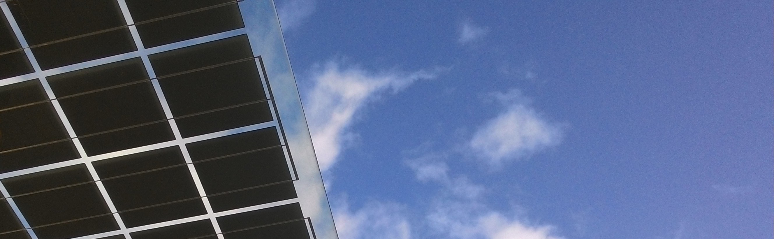
But now to the actual case. A colleague from Austria had asked us for assistance. Involved in this case was a 100kWp flat-roof photovoltaic facility on a company’s roof where a fire broke out. Passers-by had noticed the fire just by chance. By the time the concerned company had been alerted, some solar modules were already in flames. A hole exposing the underlying insulation had formed in the non-combustible roofing film beneath the solar modules.
The insulation was flammable and had already begun to burn. Fortunately, the fire was discovered in time and the outcome mitigated. A total of 29 affected modules had to be dismantled. After the roof had been repaired, the question arose as to what caused the fire. Could the remaining solar panels be put back into operation, or would the entire facility need to be dismantled and disposed of?
To clarify this issue, we proposed performing a dark-iv-curve measurement, a reverse-current thermography, and an electroluminescence test on all module strings. From other cases, we were already familiar with the dark iv-curves of module strings in whose case, for example, arcs arise by torn cell connectors.
In one case, we were able to demonstrate how an arc ignited a solar module’s rear film.
Recognizable on the dark iv-curve, too, were poor plug connections between the solar modules also previously identified as a cause of fire.
Start of the investigations:
The facility had a total of 18 module strings: 15 strings with 22 polycrystalline 250Wp modules in series, and 3 strings with 23 modules in series. 3 of the 22-module-strings were affected by the fire. The DC lines were routed in the building’s basement by means of MC plug-connectors to 3 DC combinerboxes containing a DC disconnector. Installed above that were the three 30kW inverters. When we were about to disconnect the individual DC strings from the DC terminal boxes as part of our preliminary investigations in daylight, we were informed that fireman’s switches were also located on the roof. These were stated to be compulsory in Austria now, and had therefore been retro-fitted on the roof. The measurements of the individual module strings therefore had to take place near the fireman’s switches up on the flat roof.
Fireman’s switch insert:
For all those who do not yet know what a “fireman’s switch” is, here is a brief explanation:
The first fires which occurred on photovoltaic facilities gave rise to a discussion about the inability to fully switch off a PV facility in the event of a fire. When the inverters are switched off, the direct-current cables remain energized until the sun sets. An installation of so-called fireman’s switches was therefore proposed to protect firefighters during their firefighting operations at photovoltaic facilities. The switches comprise DC circuit breakers which possess full load switching capacity and are mounted on the roof at the start of the DC main line. The switches can be remotely operated from below via the engineering room, thus making it possible to de-energize the DC lines leading into the building. In case of a power failure, too, these switches automatically disconnect the DC lines. After switch-off, the fireman’s switch locks into place and cannot be switched on again inadvertently from below. In order to turn the switch on again, it is necessary to climb on to the roof and operate the switch manually.
Because a fireman’s switch is not the only way to counter the described threat, the alternatives will also be described here briefly:
One alternative to the fireman’s switch is shockproof installation of the DC power lines, i.e. so that firefighters are not endangered by electric shock at any time, even in the event of a fire. This is usually achieved through installation in a closed, grounded metallic conduit or through flush-mounting. Even better from my point of view, is mounting of the entire inverter station on the roof, and no routing of DC lines into the building in principle. The AC side can then be switched remotely, and the facility shut down in the event of a fire. I dealt in detail with the topics of fire and photovoltaics already a few years ago in an article in this blog.
Back to our case.
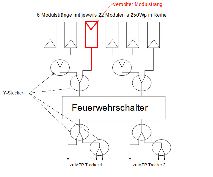
After learning about the existence of fireman’s switches, we climbed on to the roof to find them. We found them simply placed in a metal conduit. Each of the switches had 2 inputs, each accessible via MC4 panel plugs. To avoid having to install 9 of these switches for the 18 module strings, the installing technician had the idea of connecting 3 module strings in each case in parallel on the roof. However, this was done not in a DC combinerbox, but with the help of two MC-Y plugs connected in series for this purpose. After the fireman’s switch, the lines were also split with Y connectors again, thus making it possible to continue using the old cables (I have inserted a schematic diagram below).
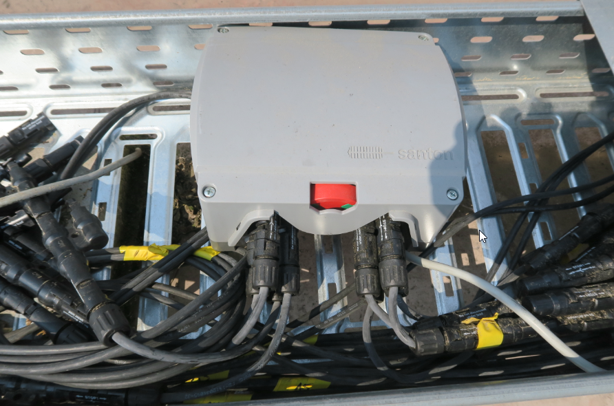
Why this type of installation was chosen is understandable. They wanted to somehow incorporate the fireman’s switch with minimum effort. “Dump” would be a better term than “incorporate”. Already at this point, I must say from the expert’s point of view: “That just doesn’t work”. Either 9 fireman’s switches are actually installed for 18 module strings, or the already present DC combinerboxes are installed on the roof, and the fireman’s switch is built into them. This is followed by parallel installation on the roof, and 6 new DC cables of a larger cross-section are installed for the 3 inverters in the basement. To be mentioned additionally is that each inverter had 2 MPP trackers.
To measure the individual strings, we first labelled them because the cables had simply been disconnected on the roof to permit installation of the fireman’s switches, without any identification of the associated module string in each case. After that, the MC plugs at the Y-connectors were opened to measure the voltage, the short-circuit current and the insulation resistance with a Benning PV1-1. All values at the first fireman’s switch were normal. The only conspicuity was incorrect crimping of the plug connectors. All positive wires were furnished with a negative plug, the negative wires with a positive plug. After polarity reversal on the measuring device, however, all strings could be properly measured. The plugs at the second fireman’s switch suddenly turned out to be correctly crimped. Except for one… but more about that later.
After observing no abnormalities on the module strings, we waited for darkness and began our measurements: Dark iv-curves, electroluminescence, reverse current thermography.
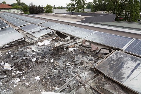
The dark characteristics showed no abnormalities whatsoever; the curves of the individual strings were perfectly superimposed. Each string was identical.
The result in the case of electroluminescence was only a few high-impedance front contacts, i.e. cells in which the current distribution was no longer uniform and in whose case one front contact resulted in a higher current than the other. Involved here were cells with only two bus bars. The thermographic test revealed no major temperature differences, however.

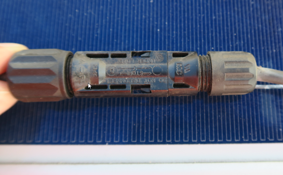
This cell fault could never have caused a fire. In the meantime I had found plug-connectors simply lying around in some places on the roof. As experienced frequently, the screw connections on the plugs were not correctly closed in some places, and cross-connections had been established on the main DC lines, i.e. at the end of the respective module strings. Cross-connections are different manufacturers’ plug connections which should be mutually compatible. In the event that such a connection fails, however, neither plug manufacturer usually provides a guarantee, because each one only tests their own plug. At this point, all installing technicians are therefore strongly advised against establishing such connections. The warranty risk ultimately always remains with the installer.
I therefore suspected the plug connections. However, I was not absolutely sure.
Because the weather the next day was forecast as very good, we decided to measure the illuminated characteristics of all module strings the next day, in addition to the investigations in the dark. Perhaps this would make it possible to obtain additional findings.
Although heavy traces of module soiling were evident on the illuminated characteristics measured the next day, there was no indication of how the fire could have been caused.
We again only had to struggle with these silly connectors which had been crimped the wrong way around on some strings. The positive plugs were on the negative wires, and vice versa. We had to constantly reverse the polarity of our characteristic measuring device. Already the day before, I had pointed out to my colleague that these plugs would need to be replaced so that two strings are not connected in series by mistake.
But the decisive flash of inspiration came when my colleague asked whether the wrong plugs would already allow current feedback from one string to another via the Y-connection?
Suddenly then, we realized the disaster. At all Y-connectors, all positive lines were furnished with positive plugs, or all negative lines with negative plugs. Except for one Y-connection. In this case, there were two of one kind, and one of the other. And those were exactly the 3 strings affected by the fire. I must add that the 3 remaining strings (29 burnt modules had already been removed from the roof) were closed again with a DC extension, so that we could still measure the remaining modules. The planned parallel connection of 3 module strings had accordingly not taken place there.

Instead, 2 strings were connected in parallel, and this parallel combination subsequently connected in series to the third string.
To better understand what exactly happens when two parallel strings are connected anti-parallel to a third module string, I drew a diagram in which two parallel solar modules are connected with a third module in anti-parallel. The principle here is similar. Only the power dissipation in the cells is lower, and there is no immediate breakout of a fire.

As indicated in the image, a short-circuit current is more or less the outcome. However, the two parallel strings can drive a current twice as high as the single string with reverse polarity. This resembles a short-circuited module string in whose case some cells are shaded by half. The bypass diodes of these modules would immediately become conductive, because the shaded cells are not able to carry the full short-circuit current. In our case, the string with reverse polarity is unable to carry the double short-circuit current, so that its bypass diodes become active. However, these diodes are only designed to conduct a single-fold short-circuit current for a certain time. If an attempt were made to pass a higher current through for a longer time, the first diodes would eventually fail and the current would only be able to flow through the solar cells.
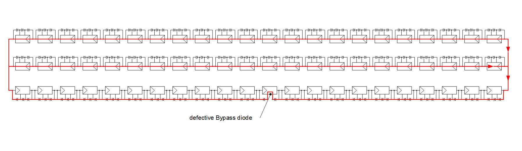
A solar cell operating above the short-circuit current is nothing more than a diode in the reverse direction. This diode can absorb a maximum reverse voltage of 14-15 V before breaking down electrically. In electronics, this phenomenon is known from Zener diodes which are designed specially for operation in the breakdown region. Solar cells are not designed for this, and become extremely hot very quickly. Now a bypass diode always bridges 20 solar cells in a 60-cell module, so that a voltage of 280-300V is necessary to bring all 20 cells to the breakdown point. The voltage of the two parallel module strings in our example suffices easily for this. In full daylight, about 18A are driven by the two parallel strings. At a voltage of 300 V, the power dissipation in the 20 cells accordingly is up to 5.4 kW. Apparently, the resultant heat is large enough to ignite the rear foil at some stage, causing the entire module to ultimately burst into flames.
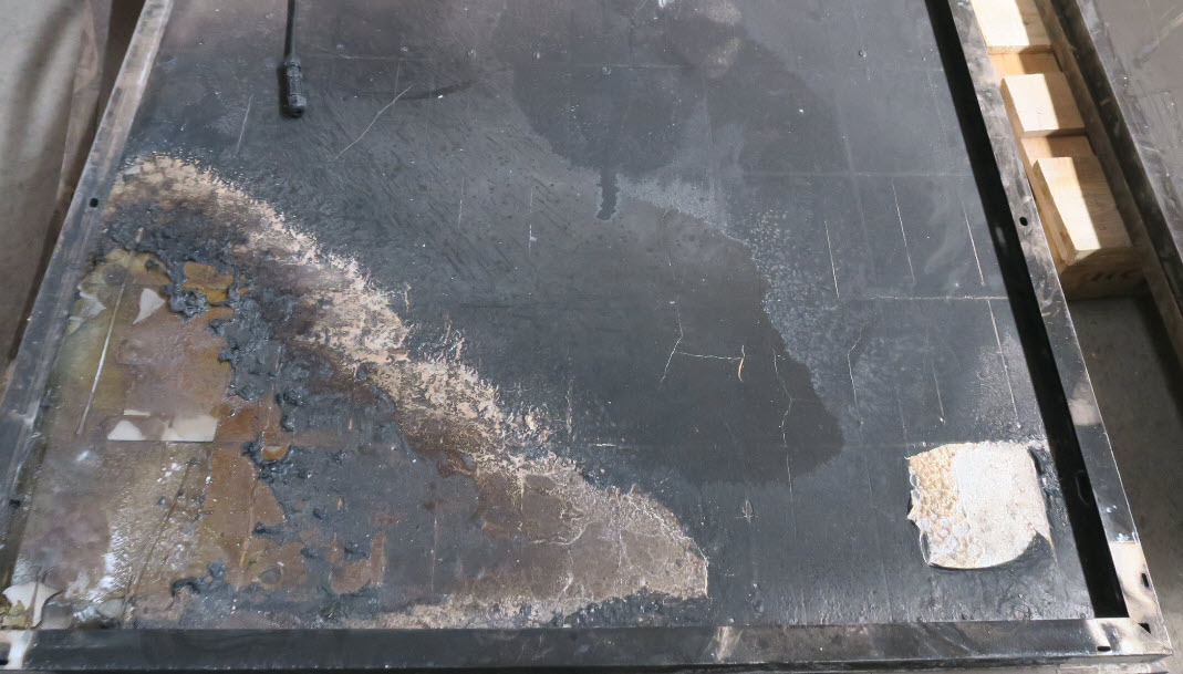
The overall effect of this is demonstrated in the photos in this article. Under unfavourable circumstances in which a combustible insulation is located underneath the roofing membrane, the whole roof could therefore ignite in the worst case.
This example shows how important it is to prudently install the DC lines for a photovoltaic facility. Prudent installation includes mounting a high-grade DC combiner box in which all module strings are safeguarded at the positive and negative ends by means of special DC fuses, all of which must be capable of absorbing the full open circuit-voltage. It is furthermore irresponsible to operate large photovoltaic facilities without any monitoring at the string level.