
One type of fault that we have encountered quite often recently is that of open cell connectors on single solar modules in a module string. I have already described this issue in the article on the causes of reduced open-circuit voltage in solar generators, but I have now decided to revisit the topic in more detail because it is so important to detect these faults at an early stage. The title gives you an idea of why this is the case. The article is aimed at the more technically proficient readers and is likely to prove tough going for non technicians.
The series connection between the individual cells in a solar module can sometimes break at one or more points. This can occur in a variety of locations. We have seen it in the module junction box when, for example, the contacts on a spring clip had corroded.

This is the simplest case to solve, as the contact point can usually be restored if the fault is discovered in time. When the fault occurs in the laminate, the outlook is not so good, as it is impossible to gain access to remedy the fault.
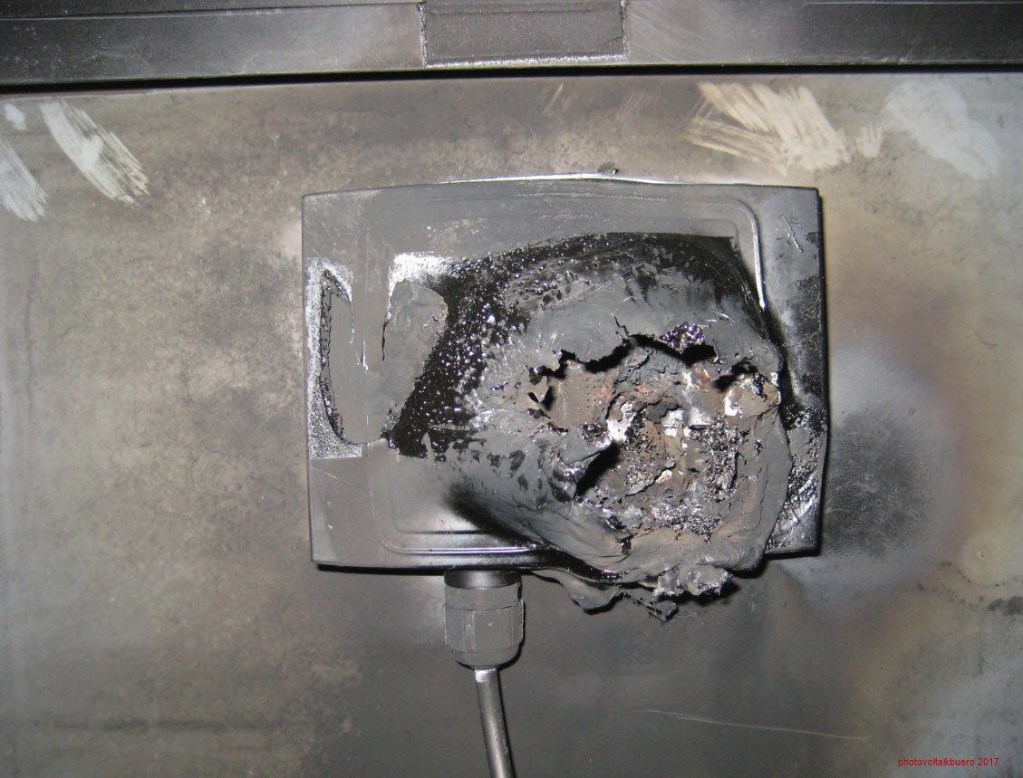
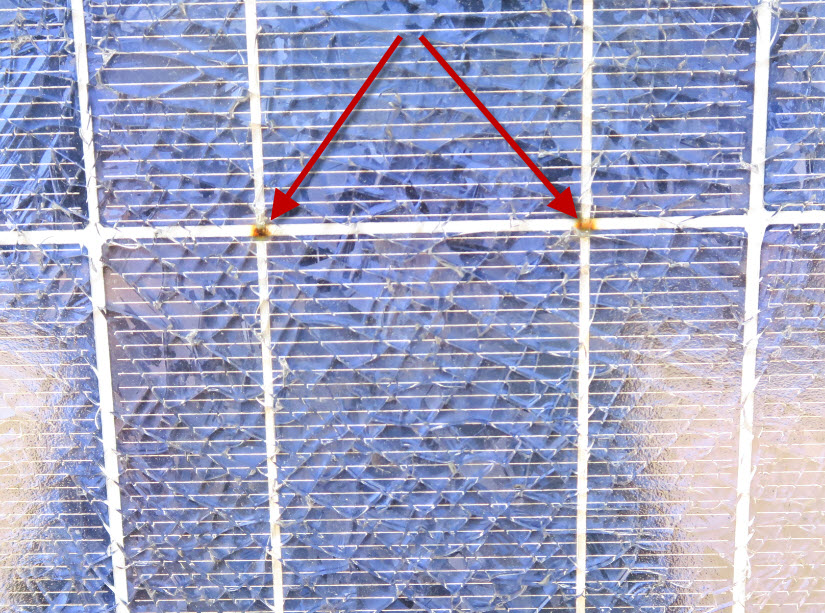
Unfortunately, these breaks, which can occur either between two cells or on the upper cross connections, cannot be repaired at a reasonable cost and usually require the replacement of the modules affected. If, as in the case shown below, the module glass panes are already cracked, the module will have to be replaced anyway.
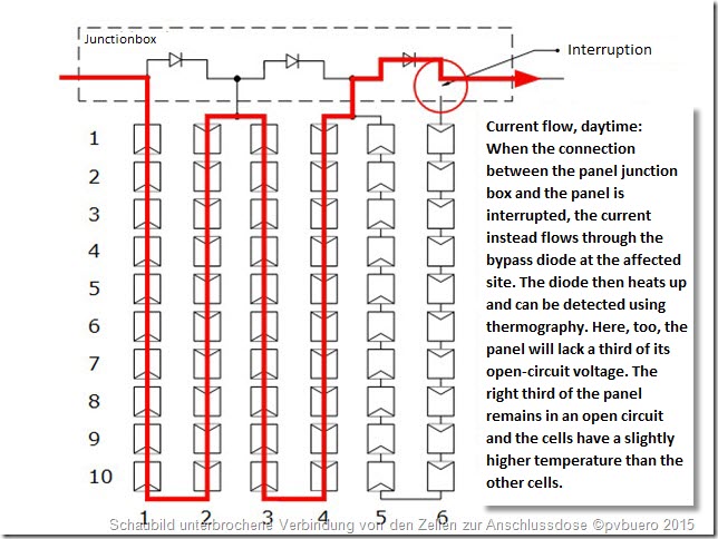
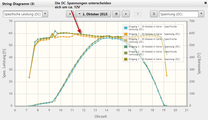
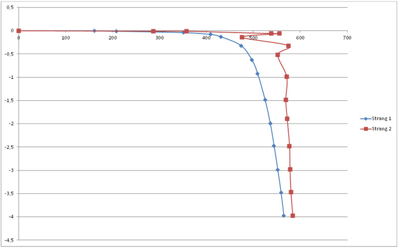
Because we are normally concerned with finding efficient ways of troubleshooting solar power systems here in the blog, I would like to describe how to troubleshoot the fault using the various investigation methods available to us. For our purposes, it would make sense to assume that the fault has not led to a failure of the module string. As each substring in a module, which is usually made up of 20 to 24 solar cells, is always bridged by a bypass diode, an open connector will cause the open circuit voltage of all the cells in the substring to drop (by about 0.5V) at the break point. As a result, the bypass diode will receive a positive voltage and become conductive, and the string will continue to operate at a reduced open circuit voltage. The first way to locate this fault is also the easiest. Always measure the open circuit voltage of the individual strings in comparison to a reference string and check the voltage difference between the two strings (assuming the same string length). If the voltage difference is in the region of 11-13V, you need to take a closer look at the string. Incidentally, a good monitoring portal will also detect these voltage differences without anyone having to physically access the system.
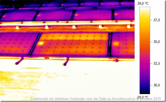
If you are on-site, however, a thermographic inspection is the easiest way to locate the fault. Of course, this requires a decent irradiation level of at least 600W/m². Now we come to the famous question from my troubleshooting seminar: “When does a solar module reach its highest temperature, at no-load, at the MPP (maximum power point) or when short circuited?”
The answer is: at no-load. You can easily explain this using the law of conservation of energy. If the module is irradiated with a specific amount of energy, it heats up until the radiated energy is exactly equal to the energy absorbed. The module is then in thermal equilibrium and its temperature no longer changes. Equilibrium is also reached, albeit at a lower temperature, if part of the irradiated energy is converted into electricity and removed from the module. This happens when the energy is sent to the inverter and is no longer able to contribute to the heating of the module. If, as in the fault described here, one-third of a module fails (most modules have 3 substrings bridged with a bypass diode), then this third will heat up slightly more than the other parts of the module running in MPP mode. From experience, we know that the temperature difference is 2-3 Kelvin. Since the bypass diode remains conductive in such cases, the module junction box will also become slightly warmer. Incidentally, you can tell from the temperature consistency between the affected substrings that you are not dealing with a short-circuited bypass diode. In the event of a short-circuited bypass diode you would observe the typical chequerboard pattern of cells at different temperatures.
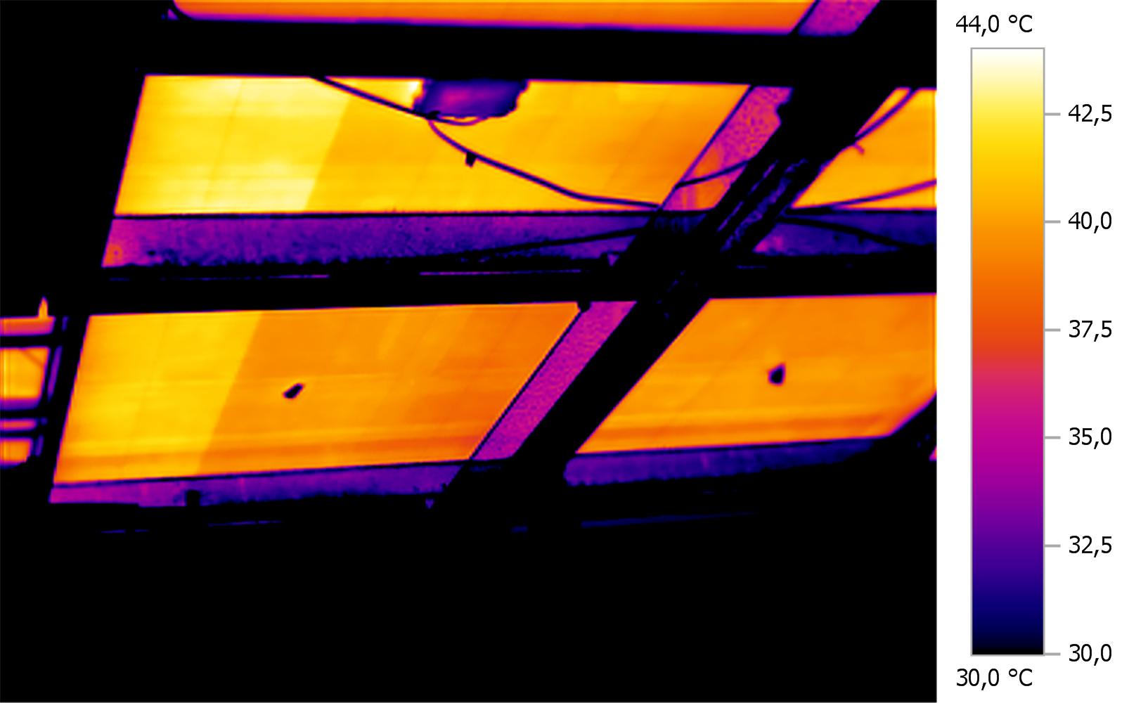
This essentially describes how you can quickly and reliably detect the existence of the fault, and locate it. What is interesting in this picture, however, is not just the final stage, when the connection is completely open, but also how the fault situation arises, and here I would refer you to back the title of this article. Let me say right now that nobody needs to panic about solar modules going up in flames. This article is only intended to raise awareness that such things can happen and that you should regularly service your photovoltaic system – just as you would a gas-fired heating system. If there is a sensible monitoring system in place and a service engineer who understands what is important, faults can be detected early.
But let’s get back to the open connector. Ideally, the contact will fail quickly and completely, with the result that the open-circuit voltage of all the cells in the substring will simply drop at the open contact. In that case, nothing more will happen; the current will simply flow through the bypass diode and the voltage of the module string will be reduced by one third of the open circuit voltage. This does happen, and is not in the slightest bit dangerous. Unfortunately, there are also cases where the contact only fails completely at high temperatures when the encapsulation film expands during the day. At lower temperatures, the encapsulation film contracts and inevitably presses on the contact again. Hotspots then form in these locations because the resistance of the connector is much higher than that of a sound connector. Finding such faults is, of course, doubly difficult, since the fault (insufficient open-circuit voltage) is intermittent. We have already had cases where a reverse current could be applied to the modules without any problem and where the connection sorted itself out during the day when temperatures were higher. It was not possible to apply reverse current then. The situation becomes particularly critical when a tiny gap is formed between the open contacts that causes arcing when a voltage is applied.
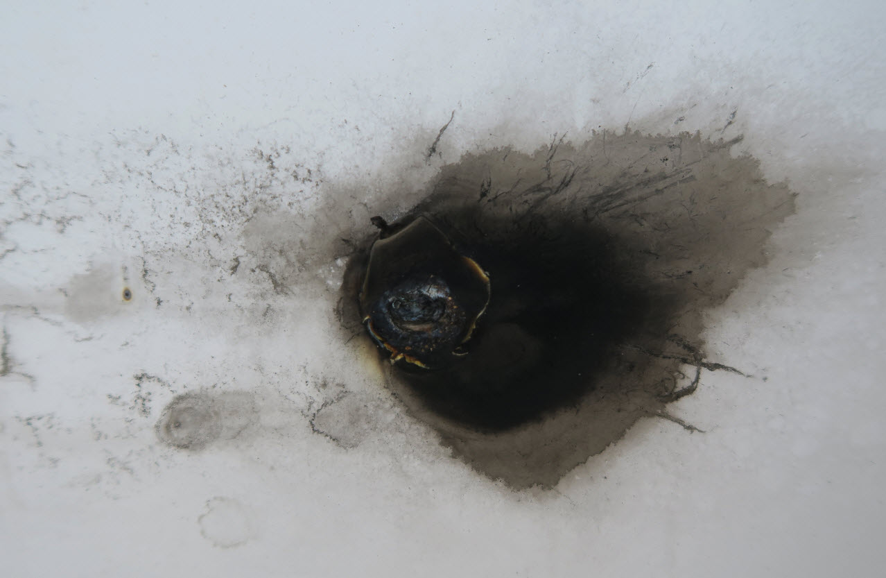
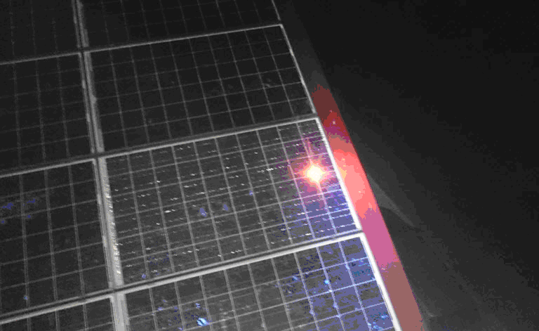
The voltage across the arc is normally limited to the open circuit voltage of all the cells in the substring. This also limits power dissipation in the arc. Nevertheless, in a worst-case scenario this could be enough to fracture the front glass. An even worse situation is when a spark ignites the backing film. These photos show the typical fault pattern with a discoloured backing film. You can see how this fault occurs in the video below. In the videos, the arc was artificially ignited with the aid of the pvServe. The test required significantly higher voltages than the open circuit voltages of 24 cells. The simulation is, however, fairly realistic. If one imagines that a bypass diode, which is permanently active and thus subject to much higher stress, is suddenly taken out, it is clear that arc voltages of several hundred volts can develop. The fact that instances of burning backing film have occurred shows that these videos work quite well to demonstrate the causes of this fault.
Reverse current
For the people who use our pvServe for troubleshooting, I would just like to say this about the fault I have just described.
As soon as a connector in a substring becomes completely detached, you can no longer apply reverse current. As previously explained, the fault can then only be realistically localised using a thermography inspection during the day. You can still apply current in the forward direction – that is, through the bypass diodes. This will enable you to clearly distinguish the fault from a severed DC cable outside the module. In cases where the contact is not yet fully disconnected, there is a risk that applying reverse current could cause arcing.
This allows the fault to be located quickly but it could also inadvertently cause a fire. It is therefore essential that you never conduct this type of inspection on your own, that you examine the energised modules carefully and that you always proceed with caution. These “wobbly contacts” can easily be detected from the fact that the voltage at the pvServe fluctuates very strongly (often by 10-40V) at a constantly regulated current. Dark I-V curves also show up bad contacts immediately.
I do hope that you are able to detect as many of these faults as possible (hopefully all of them) at an early stage in order to avoid more serious consequences and that the module manufacturers will improve their quality management to ensure that such faults eventually become a thing of the past.


Matthias,
In the first example shown above, where a ribbon connector fails, if the connector that failed was in the 2nd or 3rd spring connector, the module would behave properly, but not have access to the bypass diode. This would be an equivalent failure to that of an open bypass diode. What are the failure results when a bypass diode fails in the open position. My hunch is that if one of the 24 cells becomes shaded it will go into reverse breakdown and melt the ribbon tabs to the point of an open circuit, at which time the module will cease production and the entire string will have an open circuit, or worse an arcing circuit. I have not experienced this, and would like to know what your experience with failed bypass diodes in the open circuit mode, have taught you. Thanks.
Hello dear ,
We have a grounding PV farm located in coastal city ,
suddenly two strings damaged due to having over heated Junction Boxes each string consists of 22 panels. the junction boxes showed melted plastic due to burnt didoes inside , and the I_V curve for each panel in the faulty strings showed different behaviours ,some of them worked normally while others are not,
we asked testing company to check those strings and refereed to us by below :
Simply, what our team have found is there are some hotspots and by-pass diode issues on the modules. As we checked in details there is no problem during cable installation and no any damage on the string cables. We have checked inverter side as well and all fuses that has been used for strings are appropriate. The plus and minus cables polarity are OK and their isolation test had been tested. Junction box issue does not seem due to lighting because in that case all modules in the string should have the same issue but there are some of them working but some of them have extra temperature.
i would appreciate your support if you advise what are the reasons behind this sudden problem ? is that true that the lightening strike should damage all modules and not part of them?
awaiting your soonest feedback
all respect and appreciation for this useful site
Thanks alot
Hello Sir,
there are two kinds of defective bypassdiodes. Open bypassdiode path often with melted junction boxes and shorted bypassdiodes. Both cases are often found after overvoltage events. You need to check the whole installation.
You can do the following: Fly the installation with a thermo drone and make thermal images of the plant. 1. in open circuit mode (all inverters switched off), then in mpp mode (all inverters run).
To go even more into details you can measure the dark iv-curves of each string and each bypassdiodes-path. If the strings show some abnormality it should be checked with the electroluminescence method.
With this methods you will find all your problems.
After a lightning strike not all modules are necessarily damaged.
Best regards Matthias Diehl
Good day Sir,
Seeking your assistance with one issue.
One Table with 3 strings, each string with 27 pannels , series connected.
Pannels are 395 V and I found 14 burned – on the back of the pannel , melted Diode body frame.
The fusses, all are intact.
One voice was mentioning about a wrong AC cable polarity.
Could be the root cause ?
what doews burned mean ? On the junctionbox or the backsheet ?